Principles of Computer-aided Engineering of Thermoplastic Injection Molding: Process Settings
The article in English was originally published at smart-molding.com
Correctly set process conditions and known differences between simulation parameters and actual injection molding settings are of great importance because they help explain simulation data properly during defects prediction or scrap causes analysis. The following are the main process settings for 3D simulation of thermoplastic injection molding using Moldex3D.
Moldex3D Process Wizard
One can define injection molding process settings in Process Wizard (Fig. 1) of Moldex3D by several methods.
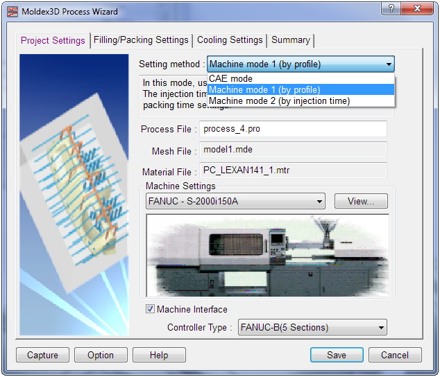 Fig. 1Â Moldex3D Process Wizard
Process Settings for a Complete Molding Cycle
The most important key parameters in a process condition for simulation can be summarized into 7 items which will be interpreted respectively below:
1. Injection Speed & Profile
Volumetric flow rate is one of the most important process settings of thermoplastic injection molding. Flow rate affects the appearance and the layered structure of molded part, orientational thermal and residual stress, shrinkage, mechanical and other quality characteristics of injection molded parts. A too high or too low flow rate can cause various types of unstable filling and other problems.
Process Wizard sets flow rate in the same manner as in actual injection molding machines, with a stepwise (Fig. 2) or a linear flow rate profile. Moldex3D automatically takes into account melt compression in heating cylinder during injection.
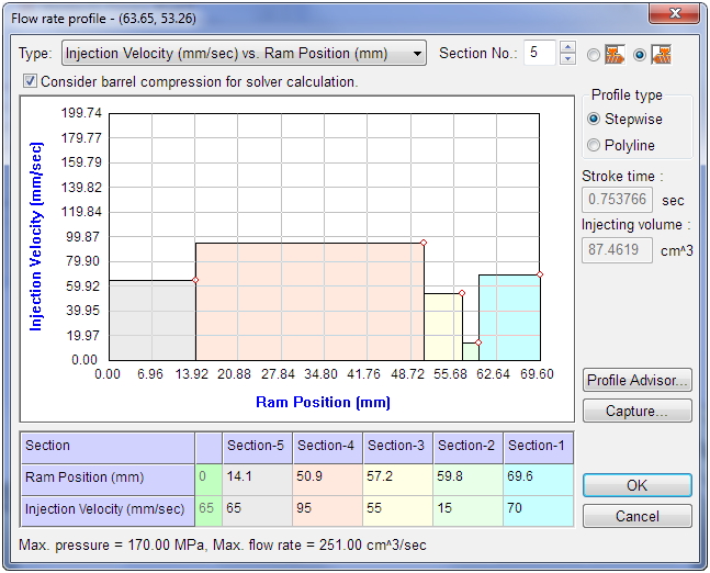 Fig. 2Â Setting a stepwise flow rate profile
2. Injection Pressure
Injection pressure is set as a profile both in actual injection molding and in simulation environment. As at the injection phase under normal process conditions (with no flow instability and no air captured in mold cavity), melt pressure at flow front equals atmospheric pressure, maximum injection pressure equals pressure drop along the flow path. The dependence of maximum injection pressure on flow rate (for a wide range of flow rates) has a minimum (Fig. 3).
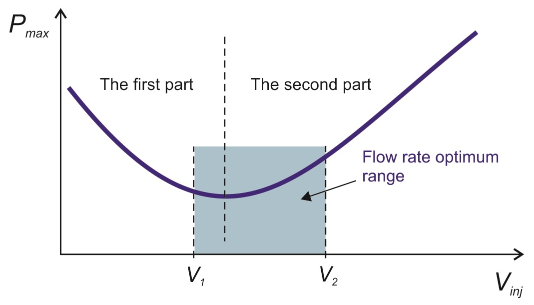 Fig. 3Â Maximum injection pressure (Pmax) versus volumetric injection rate (Vinj) with pressure drop (1st part)
and increase (2nd part) intervals; flow rate optimum range (V1 to V2)
3. Melt Temperature
By default, it corresponds to melt temperature recommended by the manufacturer of thermoplastic material and normally equals the average point of the melt temperature range.
Fig. 4 shows some injection molding problems related to melt temperature at entrance of mold cavity and to maximum pressure during injection. Reduced maximum injection pressure or melt temperature lead to short shot, whereas high maximum injection pressures lead to flash due to high average pressure in mold cavity.
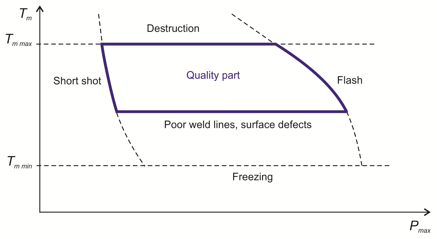 Fig. 4 Melt temperature (Тm) versus maximum injection pressure (Pmax) and typical injection problems;
Tm min is the minimum melt temperature, Tm max is the maximum melt temperature
4. Packing Pressure & Profile
Both for an actual injection molding process and when simulating packing phase, pressure profile is set either stepwise or linearly in time (Fig. 5). Packing pressure at each step may be set as an absolute or a relative (to maximum packing pressure) value.
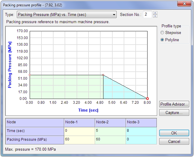 Fig. 5Â Setting a packing pressure profile with linear pressure decrease
Initial packing pressure determines melt flow rate in mold cavity at filling phase after switching to pressure control mode. A low initial packing pressure during injection molding of large, thin-walled and other parts can lead to cooling of melt front and, hence, cause surface defects, high residual stress, etc. A too high initial packing pressure results in a high melt flow rate when finishing mold cavity filling, which can also cause high residual stress and other problems.
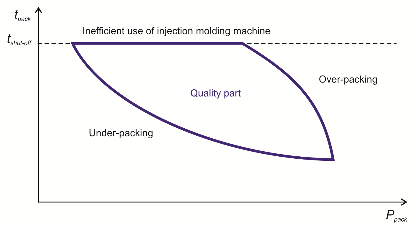 Fig. 6Â Packing time (tpack) versus packing pressure (Ppack) diagram and packing issues
5. Packing Time
Packing time is normally set to be slightly greater than the time before mold cavity is disconnected from heating cylinder. One can determine this time automatically or manually by several methods: by stabilization of part weight in time, by sharp reduction of melt flow through a gate, etc.
6. Mold Temperature
The simplest option when simulating molding cooling process in Moldex3D is to set a uniform mold temperature. If one simulates mold cooling process taking cooling channels design into account, the mold temperature distributions will be determined by process settings including coolant temperature and flow rate (Fig. 7). Flow rate of coolant is set to ensure turbulent coolant flow in cooling channels (recommended Reynolds numbers: 5,000 to 10,000
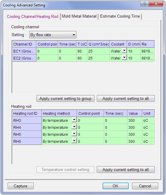 Fig. 7Â Process settings for mold cooling channels and heaters of a hot runner system
7. Cooling Time
As a rule, one sets cooling time to ensure molded part is cooled down to a required ejection temperature. A too early part removal from the mold results in part warpage. However, one can normally remove thick-walled items with sufficiently high rigidity (produced from a thermoplastic material with high modulus of elasticity) from the mold without waiting for their full interior solidification. A notable exception is parts with high dimensional precision requirements.
Increased cooling time reduces warpage of parts (thanks to stress relaxation), but reduces injection molding equipment performance, making cycles longer.
Optimization of process settings
Moldex3D includes several methods aimed at optimizing injection molding process settings. For quick evaluations, one can use algorithms of automatic determination of flow rate and packing pressure profiles by simply pressing Profile Advisor button in Process Wizard (Fig. 2 and 5). These algorithms employ data from previously performed simulations for the same mold and thermoplastic material grade.
Moldex3D Expert module provides a rating of process settings that affect output process characteristics, and helps finding an optimum injection molding mode using design of experiments techniques.
Aluminum Square Tube Profile,Aluminium Extruded Profile,Extruded Aluminum Products,Extruded Profile Line
Guangdong Huachang Group Co., Ltd. , https://www.gdhcaluminum.com
