
Improvement of Water Level Protection of Boiler Drum in Daba Power Plant
I. Brief description of the current situation The four boilers of the 300MW unit in the Daba Power Plant are all natural circulation boilers produced by Beijing Bage Company. The rated evaporation is 1025t/h, the main steam pressure is 16.8MPa, and the main steam temperature is 540°C. Drum water level protection is a main protection of the boiler. Designing as one of the MFT conditions of BMS (Boiler Burner Management System) is a very important fire protection condition.
The design principle of the drum water level protection interlocking condition and logic originally designed by our factory is: the alarm signal is issued when the drum water level is high or low I (fixed value 50mm); the signal is sent when the water level is high H value (100mm), and the Open the accident and release the water gate; when the water level reaches a low I value, the associated accident discharge valve is released; a low water level II value (100mm) sends an alarm signal: an alarm signal when the water level is high III (+200mm) or low III (200mm), At the same time send signals to the MFT loop, MFr action, boiler fire.
In the drum level measurement, we used four water level measuring instruments. One is the local bull's-eye water level gauge, accompanied by an industrial television camera system that introduces signals into the television of the control room, allowing the operator to remotely monitor the water level. The second type of water level gauge is a mechanical differential pressure level gauge, which has been installed on the unit operating platform 12.6 meters, its advantage is that without any power supply, the operating personnel can still monitor the steam when the power of the instrument control power is lost. Water level. The third type is an electrical contact level gauge, installed in a centralized control room. Its characteristics are accurate measurement, high reliability, and low maintenance. The fourth is to use 1151 differential pressure transmitter to measure the water level, and then use the parameters such as the pressure of the steam drum to correct it. Its characteristic is that it can continuously measure and record the water level signal that can directly participate in the automatic adjustment. Its disadvantage is the transmitter. The stability and tightness of the instrumentation and balance vessels are required to be high, and other measurement parameters, such as the pressure of the steam drum, must be added. The system maintenance volume is large. In order to improve the reliability of its measurement, we used three transmitters and three sets of balance vessels. The three signals were sent to the CCS system for correction, and then the average value was used as the final steam drum to participate in automatic adjustment and interlocking. Water level signal.
The equipment used by our plant's CCS and BMS control systems are N-90 and INFI-90 equipment of the United States Bailey Co., which is a distributed control system. Therefore, the measurement, correction, automatic adjustment, and over-limit protection of the water level of the drum are all in the N. A 90 (phase 1) and INFI-90 (phase II) are achieved. This system is characterized by high computing speed, high communication speed, redundant design, high precision of digital processing, high system reliability, convenient configuration, simple man-machine interface, and easy operation.
Our #1 and #2 units were put into production in 1990 and 1991 respectively: Units #3 and #4 were transferred to production in 1997 and 1998 respectively. Drum water level protection is forced to be released due to a large number of misoperations in the unit commissioning and initial trial production. The main reasons are: (1) The measurement system has large errors and the logic is not suitable: (2) The protection logic is incomplete: (3) ) The protection interface is not reliable.
Second, the improvement program 1995-1997, we according to the needs of automatic adjustment of the drum level, the water level measurement system for the drum in-depth study. For the problem of large deviations in the water level measurement of the drum and changes in the random load of the water level measurement error, we have calibrated the measurement cylinder and the balance capacity zero: recalibration of the zero range of the 1151 transmitter; pressure on the water level, The temperature correction curve was corrected. Through a large number of complex plant operations, the deviation between the measured value of the electric level of the water level in the drum and the measured value of the 1151 transmitter is controlled within ±50 mm, and the most stable day is small and ±30 mm, and the water level deviation random group load change is eliminated. The phenomenon of decrease in the number of people is such that the deviation value of the water level meter is fixed within a certain range. In this regard, we have mainly solved the following important technical issues.
1. The treatment of the temperature measurement on the steam side of the single-chamber balancing vessel is due to the structural characteristics of the single-chamber balancing vessel, and its water temperature is a gradient distribution according to the vertical height. The temperature distribution of the measuring cylinder of our factory is generally about 50°C at the bottom and about 110°C at the upper part of the bobbin, so it is difficult to calculate it as a fixed value in the cylinder temperature, and this temperature is critical for the calculation of the specific gravity of the steam side water. In order to calculate the specific gravity p of the water in the balance vessel, we use the integral method to solve this problem (Figure 1), namely:
1L
Pa=—∫F(p)dl
L0
Through the look-up table and calculations, the water level and рa are basically solved.
The relationship, so that the type of p, only with the drum pressure.
L(рa-рs)-ΔP
â–³H=___________________-H0
Ð w-Ñ€s
In the formula, ΔH is the value of the water level deviation from zero; H0 is the distance from the water level sampling hole of zero water level; ΔP is the pressure difference generated.
Then F1(x) = f: (P steam drum): F2(x) = (P steam drum) That is, F1(x) and F2(x) are functions of the drum pressure P.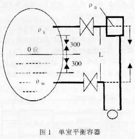 By looking at the graph, it is easy to draw a function graph of Fl(x), F2(x), and P. In addition, we found that in the north, the temperature of the equilibrium vessel in the winter and summer is not the same, which requires the thermal worker to continuously measure the temperature distribution and correct the p in time. To ensure that the water level correction is accurate. Our next step is to install a thermocouple element on the outside of the balance vessel and introduce the temperature of the equilibrium vessel into the computer control system. After a manually created database, the рa can be corrected at any time by the computer. It has been proposed that the balance vessel be insulated by thermal insulation. To maintain the constant temperature, we think it is not proper, because the temperature gradient of the single-chamber equilibrium vessel must exist due to the heating and flow of the steam, and it cannot be solved by the method of adding insulation. In addition, due to the addition of heat, the temperature of the container is also difficult to measure, which is not conducive to the calculation of рa, and the insulation cannot solve the problem of рa. The use of double-chamber balancing containers, due to the need to drill the instrument tube in the down tube of the boiler, this brings certain problems to the design, installation and maintenance of the boiler, especially the long-term high-pressure steam flushing of the fine instrument tube, which also brings certain problems in safety.
For the average calculation of the three transmitter measurement corrections, we have improved. In the original calculation circuit, the three-way drum water level measurement value is the final drum water level value after the pressure is corrected and averaged. When the deviation between the measured value and the average value of a certain transmitter exceeds 150 mm, the station transmission is considered to be Device failure, drum level is the average of the other two transmitter measurements. In this way, when a certain transmitter instantaneously exceeds the measured value (bad quality), it first causes the average value to rise very quickly and the faulty transmitter does not cut off. In actual operation, this phenomenon occurs more frequently. In the trial operation of #3 and #4 furnaces, because of a transient fault in the transmitter, the corrected water level is +600 mm or more. The boiler has a high total fuel level due to the high water level of the drum. (MFT). After careful analysis and study, we adopted two methods to solve this problem: First, reducing the deviation between a single value and the average value to 60mm is one of the conditions for removing a single transmitter: Second, any change When the deviation between the transmitter and the other two transmitters is greater than ±100 mm, the transmitter is immediately excised.
2. Improving the protection logic In the improvement of the protection logic, we have done a lot of experiments and trials on the reliability of the protection according to the lessons learned from the 1997 Qinhuangdao Power Plant boiler drum water level protection accident. First of all, in the logic of the immediate MFT of the boiler after the average value of the original drum water level exceeds the limit, plus three transmitters with two or more transmitter water level limit conditions, two conditions "and" after the action MFT . In addition, any two transmitters have been automatically removed for protection against failures, and the operator is reminded to prevent misoperation. The specific logic diagram is shown in Figure 2.
In the protection interface, especially the protection signal sent from the CCS to the BMS interface, we canceled the communication transmission signal, to avoid the communication malfunction caused by the phenomenon of protection malfunction (this phenomenon occurred), the use of three channels from the CCS output steam The water level tripping signal is sent to the three input interfaces of the BMS through hard wiring. After three logic operations are performed on the three channels in the BMS, they are used as conditions for the MFT. In the CCS signal interface sent to the BMS, in order to prevent the CCS output DOD breakdown phenomenon (this phenomenon occurred many times), we have added expansion relays on the interface, greatly improving reliability.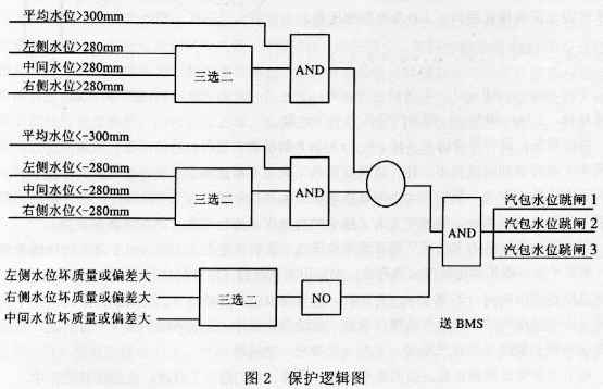 III. Implementation and Effect In 1998, we carried out a comprehensive improvement of the #1 #4 furnace drum water level protection system and put it into operation. In the actual operation of the six months, the water level protection of the steam drum was acted four times, and all the actions were performed without any malfunction or refusal, fully demonstrating the reliability of the water level protection of the steam drum.
The design principle of the drum water level protection interlocking condition and logic originally designed by our factory is: the alarm signal is issued when the drum water level is high or low I (fixed value 50mm); the signal is sent when the water level is high H value (100mm), and the Open the accident and release the water gate; when the water level reaches a low I value, the associated accident discharge valve is released; a low water level II value (100mm) sends an alarm signal: an alarm signal when the water level is high III (+200mm) or low III (200mm), At the same time send signals to the MFT loop, MFr action, boiler fire.
In the drum level measurement, we used four water level measuring instruments. One is the local bull's-eye water level gauge, accompanied by an industrial television camera system that introduces signals into the television of the control room, allowing the operator to remotely monitor the water level. The second type of water level gauge is a mechanical differential pressure level gauge, which has been installed on the unit operating platform 12.6 meters, its advantage is that without any power supply, the operating personnel can still monitor the steam when the power of the instrument control power is lost. Water level. The third type is an electrical contact level gauge, installed in a centralized control room. Its characteristics are accurate measurement, high reliability, and low maintenance. The fourth is to use 1151 differential pressure transmitter to measure the water level, and then use the parameters such as the pressure of the steam drum to correct it. Its characteristic is that it can continuously measure and record the water level signal that can directly participate in the automatic adjustment. Its disadvantage is the transmitter. The stability and tightness of the instrumentation and balance vessels are required to be high, and other measurement parameters, such as the pressure of the steam drum, must be added. The system maintenance volume is large. In order to improve the reliability of its measurement, we used three transmitters and three sets of balance vessels. The three signals were sent to the CCS system for correction, and then the average value was used as the final steam drum to participate in automatic adjustment and interlocking. Water level signal.
The equipment used by our plant's CCS and BMS control systems are N-90 and INFI-90 equipment of the United States Bailey Co., which is a distributed control system. Therefore, the measurement, correction, automatic adjustment, and over-limit protection of the water level of the drum are all in the N. A 90 (phase 1) and INFI-90 (phase II) are achieved. This system is characterized by high computing speed, high communication speed, redundant design, high precision of digital processing, high system reliability, convenient configuration, simple man-machine interface, and easy operation.
Our #1 and #2 units were put into production in 1990 and 1991 respectively: Units #3 and #4 were transferred to production in 1997 and 1998 respectively. Drum water level protection is forced to be released due to a large number of misoperations in the unit commissioning and initial trial production. The main reasons are: (1) The measurement system has large errors and the logic is not suitable: (2) The protection logic is incomplete: (3) ) The protection interface is not reliable.
Second, the improvement program 1995-1997, we according to the needs of automatic adjustment of the drum level, the water level measurement system for the drum in-depth study. For the problem of large deviations in the water level measurement of the drum and changes in the random load of the water level measurement error, we have calibrated the measurement cylinder and the balance capacity zero: recalibration of the zero range of the 1151 transmitter; pressure on the water level, The temperature correction curve was corrected. Through a large number of complex plant operations, the deviation between the measured value of the electric level of the water level in the drum and the measured value of the 1151 transmitter is controlled within ±50 mm, and the most stable day is small and ±30 mm, and the water level deviation random group load change is eliminated. The phenomenon of decrease in the number of people is such that the deviation value of the water level meter is fixed within a certain range. In this regard, we have mainly solved the following important technical issues.
1. The treatment of the temperature measurement on the steam side of the single-chamber balancing vessel is due to the structural characteristics of the single-chamber balancing vessel, and its water temperature is a gradient distribution according to the vertical height. The temperature distribution of the measuring cylinder of our factory is generally about 50°C at the bottom and about 110°C at the upper part of the bobbin, so it is difficult to calculate it as a fixed value in the cylinder temperature, and this temperature is critical for the calculation of the specific gravity of the steam side water. In order to calculate the specific gravity p of the water in the balance vessel, we use the integral method to solve this problem (Figure 1), namely:
1L
Pa=—∫F(p)dl
L0
Through the look-up table and calculations, the water level and рa are basically solved.
The relationship, so that the type of p, only with the drum pressure.
L(рa-рs)-ΔP
â–³H=___________________-H0
Ð w-Ñ€s
In the formula, ΔH is the value of the water level deviation from zero; H0 is the distance from the water level sampling hole of zero water level; ΔP is the pressure difference generated.
Then F1(x) = f: (P steam drum): F2(x) = (P steam drum) That is, F1(x) and F2(x) are functions of the drum pressure P.
For the average calculation of the three transmitter measurement corrections, we have improved. In the original calculation circuit, the three-way drum water level measurement value is the final drum water level value after the pressure is corrected and averaged. When the deviation between the measured value and the average value of a certain transmitter exceeds 150 mm, the station transmission is considered to be Device failure, drum level is the average of the other two transmitter measurements. In this way, when a certain transmitter instantaneously exceeds the measured value (bad quality), it first causes the average value to rise very quickly and the faulty transmitter does not cut off. In actual operation, this phenomenon occurs more frequently. In the trial operation of #3 and #4 furnaces, because of a transient fault in the transmitter, the corrected water level is +600 mm or more. The boiler has a high total fuel level due to the high water level of the drum. (MFT). After careful analysis and study, we adopted two methods to solve this problem: First, reducing the deviation between a single value and the average value to 60mm is one of the conditions for removing a single transmitter: Second, any change When the deviation between the transmitter and the other two transmitters is greater than ±100 mm, the transmitter is immediately excised.
2. Improving the protection logic In the improvement of the protection logic, we have done a lot of experiments and trials on the reliability of the protection according to the lessons learned from the 1997 Qinhuangdao Power Plant boiler drum water level protection accident. First of all, in the logic of the immediate MFT of the boiler after the average value of the original drum water level exceeds the limit, plus three transmitters with two or more transmitter water level limit conditions, two conditions "and" after the action MFT . In addition, any two transmitters have been automatically removed for protection against failures, and the operator is reminded to prevent misoperation. The specific logic diagram is shown in Figure 2.
In the protection interface, especially the protection signal sent from the CCS to the BMS interface, we canceled the communication transmission signal, to avoid the communication malfunction caused by the phenomenon of protection malfunction (this phenomenon occurred), the use of three channels from the CCS output steam The water level tripping signal is sent to the three input interfaces of the BMS through hard wiring. After three logic operations are performed on the three channels in the BMS, they are used as conditions for the MFT. In the CCS signal interface sent to the BMS, in order to prevent the CCS output DOD breakdown phenomenon (this phenomenon occurred many times), we have added expansion relays on the interface, greatly improving reliability.
Hardware Display Stand,Display Kiosk Rack,Metal Card Display Stand,Sheet Metal Steel Frame
Guangdong Dongji Intellingent Device Co.,Ltd , https://www.djmetalwork.com